Arduino Nano
And TFT lcd Turtorial
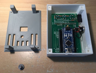
This is a very interesting project that i decide to build and
share wit you all, It requires an Arduino Nano, A TFT LCD with in-built card
reader, and a few custom built PCBs.
Three push buttons are exposed to the front of the enclosure .
The Robomart the stage for the creation of this kit can be
developed that cover some aspects of the software described.

Step 1:Required part’s
- Two layer Printed CIrcuit Board (PCB)
- 1.8" TFT LCD with SD Card Reader/Writer
- Arduino Nano
- Resistors for three buttons on an analog pin
- Pushbuttons
- Back of 3D Printed Case
- TFT LCD Backlight Jumper
- Six Pin Header
- Front of 3D Printed Case
- DHT-11 Temperature/Humidity Sensor
- Three Connector Patch Cable
- Four Sixteen Pin Headers
- Power Socket
- Screws for Case
- Nano Reset Button Extender
ITEM --- Search Terms for Items Purchased from robomart
·
1.8" TFT LCD with SD Card
Reader --- 1.8" Serial SPI TFT LCD Display Module +128X160
PCB Adapter Power IC SD Socket
·
Power Socket --- 2.1mm x 5.5mm Round
Panel Chasis Mount Female Socket DC Connector Jack Plug
·
Pushbuttons --- Quality Momentary
Tactile Push Button Switch SPST Miniature/Mini/Micro/Small PCB
·
Six Pin Header --- Stackable Si Pin Header
for Arduino
·
Breakable Headers --- Gold Breakable 40 Pin
Header Male Female 2.54mm Socket Connector Way SIL Single
·
Resistors --- 0.25W Carbon Film
Resistor 10kΩ
·
Screws for Case ---- Stainless Steel No2 x
1/2" Pozi Countersunk Self Tapping Screws M2.2 x 13mm
·
Backlight Jumper ---- 2.54mm Circuit Board
Shunts Short Jumper Cap
·
Connector Patch Cable ---- Male
to Female Jumper Wire Ribbon Cable Pi Pic Breadboard Arduino
NOTES
· " Brittle headers " for a three- pin jumper backlight four 16- pin headers for Arduino -and- ( the latter for the former and female to male ) are used as the source .
· Luca performed under a number of different 1.8 SPI 1.8 " TFT LCD module out there . Only the PCB fits that are marked with another case " are ".
Step 2: Cut the Header Strips to
the Sizes Needed
15- pin header strips at each of the four segments ( 10 ) Crop . The size using a small wire cutter to cut these strips is easy . Reduction ( in this case the end of the 16 -pin ) and the squeeze is being built , where the bus pin position on the wire clipper jaw . The pin was set , will follow the cavity should be cut as beautiful .
Step 3: Solder Headers for the
Nano
Carefully PCB ( with the label side ) to the front of the solder strips up to four headers . PCB header strips will fit in with the nano inner two strips that are flush to ensure that
(see image).
All contacts have been cleanly and neatly solder points after it is installed will cover the display module is soldered double check !!! With a volt -ohm meter will test the continuity of a good thing

Step 4: Connect 5V Power Plug

If you have a two- pair wire ( not provided ) to the power plug as solder points must be soldered to the board in front of the 5V power plug ( 3 ) are planning to use , so even once it is installed will be covered by the LCD . In fact, the power plug can be installed after the fact , but it is to note that in the ideal case .
Step 5: Install LCD Backlight
Option Jumper
LCD power option three pin jumper ( 6 ) Install . The default is to leap on the side of PWM but if you need all the PWM pin ( though without brightness control ) 5V power can drive the backlight .

Step 6: Install the TFT LCD, Pushbuttons, and
Pushbutton Resistors


TFT LCD ( 2 ) Module SD card slot electrical tape should be covered under the metal . Do this away ! If electrical tape is missing , then it is bad PCB and metal via SD card slot as the contact between the pin should be replaced before proceeding !
LCD ( 2 ) and three push buttons on the reverse side of the PCB headers ( 5 ) Install . These items are mounted flush to the board and make sure that the buttons are perpendicular to the PCB surface . Contacts button on the bends PCBs long dimension ( see image ) must be facing the relative long way . It is equally the case of these buttons protroud be mounted at the same height so that important !
Finally , the LCD and pushbuttons on the other side of the board , should be placed where spots are four 10k resistors . About this later , but these resistors together with pushbuttons , the three buttons on the nano to be used that allow the input , creating a three -legged voltage divider
Step 7: Insert PCB into Case


( As you are using a socket ) to the power socket PCB socket now exposed through the holes and soldered two wires for power socket with a 3D printed matter ( 13 ) can be put in front of is
You ( a little epoxy move ) must now be kept out of the case to expose the pin to six -pin header ( 7 ) are planning on using . Looking from the outside of the case when the title to the left of the pin , bent down , and can be soldered to the PCB ground connector .
Step 8: Attach the Back of the
Case


Four screws at the back of the case ( 14 ) can be attached using . Case ( 12 ) on the back of the PCB must press against the front of the case firmly positions . Reset button extender ( 15 ) making it possible to reset an accidental loss , although it is easy to restore nanotechnology can be used to make
Step 9: Setting up the Hardware
for the Demo Sketch

Once assembled, the pin two headers are available through nanotechnology . A number of pins is used by various functions , however , that the note !
The pins are available without warning D2 , D3 , D6 , and D7 , as well as a 7- pin are A1 . Pin serial port , D0 / RX and D1 / Tx are also available . You D5 pin PWM variable instead of constant 5V light to use light if you use the backlight jumper may be available for D5 . D4 and D12 pins may also be available , but the SD card functionality is sacrificed , then
Our demo , DHT -11 temperature and humidity sensor , only one input is required . DHT- 11 as shown in the picture I used a micro breadboard half and was able to mount it in the case . From sensor data line D3 runs and 5V and ground pins on the header to highlight the power line
Equally , patch cables on the outside of the case exposes the top of the goods to be moved up by three pins
Step 10:
Overview of the Demo Sketch
The demo sketch illustrates the use of the TFT LCD, the SD Card
Reader, the three buttons connected to a single analog pin, and a Temperature
Sensor that is provided with the kit for purposes of this example (as well as
to illustrate general capabilities of the enclosure).
The program allows for the selection of four works that displays a menu:
·
Display Current Temperature and Humidity
·
Display Historical Graph
·
Adjust Backlight (with setting saved to EEProm Memory)
·
Close Log File and Stop
Step 11: Code Snippets for the SD
Card

Step 12: Code Snippets for the LCD Display

Step 13: Code Snippets for the Buttons

Step 14: Code Snippets for the DHT-11 Sensor

Step 15: Code Snippets for the EEProm

No comments:
Post a Comment